Flooring capable of 500 lb. per sq. ft. loading or stronger must be provided throughout all equipment areas used for floor-to-ceiling racks. Equipment areas designated for operator consoles (OA&MC areas, etc.) must have floors, which support at least 350 lb. per sq. foot. Existing floors with weaker ratings must be approved on a case-by-case basis.
A raised floor with cable trays above the racks or above the ceiling is the preferred room arrangement to cool the racks and carry the cables. The raised floor provides a path for the power wiring to each rack and acts as a plenum for feeding cool air to the racks. The cable trays will carry the video, audio, data, and control cables, which exit the top of the racks. For the raised floor, the tiles should be at least 15 x 15 inches and be easily removable either individually or in a group. There should be at least 12 inches of space below the floor for AC power; six inches is the minimum. If ceiling height does not allow the use of cable trays above the racks, they can alternately be placed behind the racks at the top and running parallel to the row of racks. Cable trays should be at least 18 inches wide and have sides at least 3 inches high. Trays must not have sharp edges, which would damage cable as it is pulled. Turns must be gradual, with at least a 12-inch radius at turns of 45 degrees or more. Cable tray down feeds must be provided as required by the installation details. There should be a space of between 12 and 18 inches between the rack top and the lowest point on the cable tray or the cable tray support members which every is lower. Trays must be extensible to accommodate future growth of the facility.
In the case of a raised floor, cooling air must circulate from a plenum under the raised floor up through the equipment racks and the spacers between racks and out the top of the racks and spacers. The airflow design must insure that the cabling will not obstruct the flow of air. Airflow must also be provided in front of each rack to flow into the front intake of the provided equipment.
Adequate cool air must be available for the equipment to be operated below the maximum rated operating temperature of 35 degrees C, i.e. room temperature not to exceed 20 degrees C. Special rack construction and fans (at extra cost) may be necessary to ensure proper operation. Note: For smaller facilities a width of 9” and a rung spacing of 9” are adequate.
rack requires an additional 20 amp utility power circuit for roll-around test equipment.
Power connections will be made under each rack when a raised floor is employed. The integrator will provide a cable mount isolated ground male, type L5-20P for connection to a customerGeneral Contractor-supplied i isolated ground female, type L5- 20R, which should be mounted below or on the raised floor in an outlet box (Note: Twistlock®, and orange nylon single face, Hubbell or equivalent: 20 Amp #IG-2310-A may be used).
Two separate phases of 120 volt 20 amp power, each on a separate connector, should be provided for each rack. The use of two separate power phases provides additional protection if one phase were to fail. If power from only one phase is available, two 20-amp power connections from the same phase must be provided. The systems integrator will recommend the proper allocation of equipment to each phase. The cable supplied by the systems integrator to connect the rack AC power strips to building power will be six feet long, maximum, to conform to electrical code.
If a raised floor is not possible, AC power may be fed to the top of the rack in conduit or other shielded casing. Connection details to the rack power strips will be worked out on a case-by-case basis.
The power feed to the racks must have at least three conductors, be rated for a minimum of 20 Amps, and shall meet or exceed local, state, and national codes.
The utility outlet, intended for test equipment, is a duplex outlet with a separate power ground pin, which, returns to building ground (not technical ground) ground and which will be mounted in the base of selected racks. It will be wired in parallel with one outlet in the front of the rack and one in the rear. The systems integrator will supply these outlets, with the same connector and cord as specified above in Section 3.1/3.2. The power feeds for these outlets should be a female connector in a box as specified in section above, positioned below the racks. If the equipment room dimensions are small, in rack utility power is not required.
A “technical ground” must be provided. Briefly, this is a ground either within or outside of the building, which is completely separate from any existing power ground. The “technical ground” system is described in the attachment to this document. The provision of this technical ground does not ensure proper operation of the equipment but provides the necessary ground as may be required.
Power should be un-interruptible and must be conditioned as “technical power” and have an isolated ground. This power must be filtered to prevent voltage spikes and regulated to be in the range of 110 to 125 volts, regardless of load or short-duration variations caused by the start up of large machinery.
Adequate power must be continuously available to the racks 24 hours per day. If, for any reason, power must be interrupted, the systems integrator must be notified at least 24 hours in advance of such shutdown to properly plan our work. Customer The General Contractor agrees that the duration of the power outage will not exceed 12 hours. For worker safety and test procedures, integration engineers access must be provided access to the circuit breaker panels, which control the power to the racks.
The circuit breaker panels should be located on the walls convenient to the rack.
Sufficient floor space must be provided for the number of racks required. A standard equipment rack has dimensions of: 22 1/8 inches wide x 30 inches deep x 87 ¼ inches high. In some cases, an equipment rack may be 24 inches deep.
Minimum access to each rack is as follows:
Any building construction or remodeling in the area or affecting the area where installers and engineers will work, must be complete and free of trades before installation begins.
The technical areas will require both general and task lighting systems. While general room lighting is required for room and equipment maintenance, dimmable task lighting will be required within the operational environment. The location of task lighting should be coordinated with the control console and rack layout. Lighting should be directable, to provide a narrow beam focused on the work surface and avoid glare on the monitors.
The backside of the equipment racks and operating consoles will require good illumination (60 - 100 fc) for servicing. Dimmer controls should have the ability to change light levels in different zones for some of the operation areas. Dimmers used for control of task lighting should be of the noise-suppressed type, to avoid electrical interference with sensitive electronic and computer equipment. Dimmers should be autotransformer or variac type.
Power for the general and task lighting should be distributed from utility power panels separate from the technical power distribution to ensure the integrity of the conditioned technical power.
Adequate ventilation (heating & cooling) for all work areas shall be provided 24 hours per day, seven days per week if the installation process requires it. The HVAC system should be controllable from a thermostat within each room, with around the clock 24-hour temperature control available in all technical areas. In response to equipment heat generation, increased cooling capacity may be required to maintain the comfort zone.
Fire protection apparatus, if required by state or local codes, must be installed, tested, and functioning. In any case, an adequate supply of CO2 portable extinguishers shall be available in each location. Water sprinkling in the technical equipment areas should be avoided unless required by local codes, since it can cause serious damage to electronic equipment if the sprinklers were to go off accidentally.
The customer General Contractor shall furnish the necessary openings and ducts for cable and conductors in the ceilings, floors and walls as required by the systems integrator. These will be identified on the floor plans and will be confirmed during the meetings between the parties.
Operating telephones must be available in the equipment area. The minimum is one instrument in the rack area and one adjacent to cController desks at each location.
Access to the building must be in place and the loading dock operational so that trucks and/or tractor- trailers can pull up to it.
A road, passable by tractor- trailers, shall be in place. The systems integrator will consider unavoidable exceptions on a case-bycase basis. Provision for convenient parking must be provided.
Access to the building roof must be provided.
Keys to the buildings, gates, or any other obstruction that may hinder access to the sites must be provided to the integrators engineers and subcontractors.
Customer or the General Contractor shall provide badges or other IDs to all integrator personnel and subcontractors, if required to gain entry to all sites.
The systems integrator must be permitted access to all sites 24 hours a day seven days a week for the duration of installation and acceptance testing.
Required signal feeds from the existing plant and from other equipment not in the systems integrator’s area of responsibility must be available by the dates shown on the project plan. These feeds must be pre-equalized if required by good engineering practice, and must have proper level, eye height, and minimum jitter. The systems integrator shall produce an interface control document (ICD) detailing the parameters.
Destinations for signals provided by the systems integrator supplied equipment shall be available or arrangements previously made for access to them. The systems integrator will pre-equalize these feeds if required by good engineering practice. The systems integrator shall produce an interface control document (ICD) detailing the parameters.
Telecommunication facilities from local service providers acquired for interface to the system integrator supplied equipment shall be available at a prearranged point of demarcation. These facilities shall be pre-tested for required signal level and transmission characteristics.
As an aid to your the electrical contractor, here are technical power and grounding guidelines and recommendations for the facility.
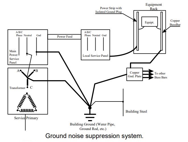
Implementing these recommendations will greatly increase the video system’s ability to suppress interference. While these standards and practices do not absolutely guarantee freedom from interference, they do provide the first line of defense.
Two basic electrical power services are required for the system: Technical Power and Utility Power.
Technical Power is supplied to the electronic equipment and shall be a separate system due to the power conditioning and isolated grounding requirement of the electronic equipment.
Utility Power shall be supplied for general room recommendations and lighting. The isolation of technical power from utility power and other building power loads minimizes the risk of equipment damage or malfunction due to power line noise and voltage spikes.
This equipment grounding system shall be a separate system from the Isolated Safety Ground system associated with the Technical Power circuits. The Equipment Ground System is created to shunt any paths to ground that may be created by the interaction of the Signal Ground, Equipment Ground and Isolated Safety Ground Systems, and therefore has the largest amount of copper and lowest resistance.